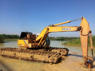
Excavator crawler driving principle
Walking power transmission route:
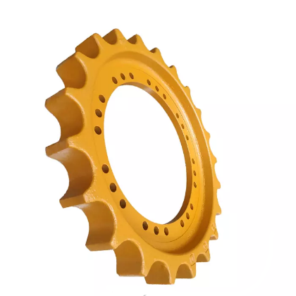
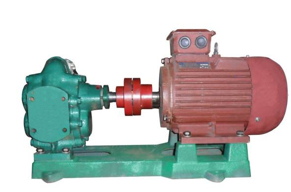
Diesel engine—coupling—hydraulic pump (mechanical energy is converted into hydraulic energy)—distribution valve—central rotary joint—travel motor (hydraulic energy is converted into mechanical energy)—reduction box—drive wheel—rail chain crawler –
to achieve walking
Extended information:
1. Rotary motion transmission route: diesel engine—coupling—hydraulic pump (mechanical energy is converted into hydraulic energy)—distribution valve—slewing motor (hydraulic energy is converted into mechanical energy)—reduction box—slewing bearing—realization turn around
2. Boom motion transmission route: diesel engine – coupling – hydraulic pump (mechanical energy is converted into hydraulic energy) – distribution valve – boom cylinder (hydraulic energy is converted into mechanical energy) – realization of boom movement
3. Stick movement transmission route: diesel engine—coupling—hydraulic pump (mechanical energy is converted into hydraulic energy)—distribution valve—stick cylinder (hydraulic energy is converted into mechanical energy)—the stick movement is realized
4. Bucket movement transmission route: diesel engine – coupling – hydraulic pump (mechanical energy is converted into hydraulic energy) – distribution valve – bucket cylinder (hydraulic energy is converted into mechanical energy) – bucket movement is realized
The driving principle of the excavator crawler:
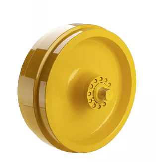
Crawler (wheel) hydraulic travel motor consists of high-speed hydraulic motor, brake, planetary reducer, valve group, etc. It is driven by the shell and can be directly connected with the wheel or the crawler driving wheel, which is reliable and efficient. It adopts the design of high-capacity tapered roller bearing, which makes it fully capable of bearing the axial and radial forces generated by the excavator during work and turning.
Hydraulic oil pumps include vane pumps, gear pumps, plunger pumps and screw pumps. Vane pumps, gear pumps and plunger pumps are generally used in the market. The vane pump can be divided into variable vane pump, heat dissipation variable vane pump, variable vane pump with cooling pump and quantitative vane pump.
The hydraulic oil pump is composed of four parts: the pump body, the rectangular fuel tank, the pressure handle and the ultra-high pressure steel wire braided hose. , which powers the entire hydraulic system. The structural forms of hydraulic pumps generally include gear pumps, vane pumps and plunger pumps. There are three types of hydraulic oil pump joints: straight-through type, self-sealing type and quick joint.
The following describes the vane pump, gear pump, plunger pump. 1. Approximate shape of gear pump:
Its most basic form is that two gears of the same size mesh and rotate with each other in a tightly fitted housing. The inside of the housing is similar to an “8″ shape, and the two gears are installed inside. body fit tightly. The material from the extruder enters the middle of the two gears at the suction port, fills the space, moves along the casing with the rotation of the teeth, and finally discharges when the two teeth mesh.
2. Approximate shape of vane pump:
It is composed of rotor 1, stator 2, vane 3, oil distribution plate and end cover. The inner surface of the stator is a cylindrical bore. There is an eccentricity between the rotor and the stator.
3. Approximate shape of plunger pump:
The structural components mainly include eccentric wheel, plunger, spring, cylinder block and two one-way valves. A closed volume is formed between the plunger and the cylinder bore. When the eccentric wheel rotates for one turn, the plunger moves up and down once, the downward movement absorbs oil, and the upward movement discharges oil.

Post time: Nov-04-2022


