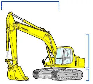
The basic structure of the excavator is divided into:
1. Undercarriage part;
2. Body part;
3. Working device part.
Working device :
-boom, stick, bucket, hydraulic cylinder, connecting rod, pin, pipeline.
Body parts
-engine, shock absorber main pump, main valve, cab, slewing mechanism, slewing bearing, slewing joint, turntable, hydraulic oil tank, fuel tank, control oil circuit, electrical components, counterweight.
Chassis part – track frame, track, idler, roller, idler, final drive, tensioning device.
body part
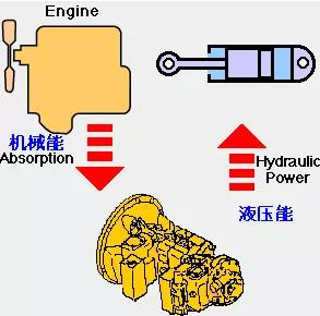
Engine—the source of machine power, converts the heat energy generated by the combustion of fuel into mechanical energy through the crankshaft connecting rod mechanism.
The main pump is connected to the engine flywheel through a shock absorber, and converts the mechanical energy output by the flywheel into high-pressure oil flow, that is, hydraulic energy.
Main valve
- divides the high-pressure oil output by the main pump according to the needs of the action of the working device, so as to realize different operations of the working device.
Slewing mechanism – it is composed of a slewing motor and a slewing deceleration mechanism, which meshes with the slewing bearing to complete the slewing action of the machine at any angle.
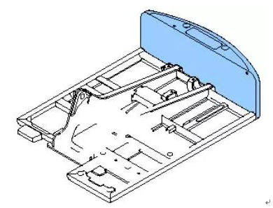
Counterweight
- Make the center of gravity of the machine as close as possible to the center of rotation of the car body to ensure the dynamic stability of the car body, reduce the rotational resistance of the slewing bearing, and achieve fast and stable rotation.
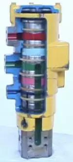
Center rotary joint
– when the machine rotates in any direction, the hydraulic oil flow of the upper body is continuously supplied to the travel motor at the lower part of the body through the internal rotating oil channel, and each oil channel inside the rotary joint is anti-wear Good performance and high pressure resistant seals are separated.
Cab
– The interior is equipped with joysticks, electrical switches, monitoring panels, air conditioners and radios, etc. The driver’s seat can be adjusted according to the operator’s requirements。
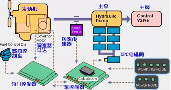
Electrical control system
Combined control of main pump and engine to achieve power matching and fuel saving
Fast Power Boost
Working mode selection
touch down mode
Auto downshift mode
Walking speed selection
Swing brake function
Automatic engine warm-up and overheat prevention function
Working device part
Boom cylinder
- two cylinders are installed on both sides of the boom to adjust the digging height and digging depth of the machine operation through their telescopic motion.
stick cylinder
- Installed on the upper part of the boom, through its telescopic movement to realize the front and rear movement of the stick (forearm), to carry out the excavation or unloading of the stick.
Bucket oil cylinder
- installed on the upper part of the stick (forearm), through its telescopic motion, the bucket excavation and unloading operations are realized.
The entire working device needs to pass the compound action of each working device in the operation process, so as to better realize the fast, time-saving and high-efficiency operation function.
Undercarriage parts
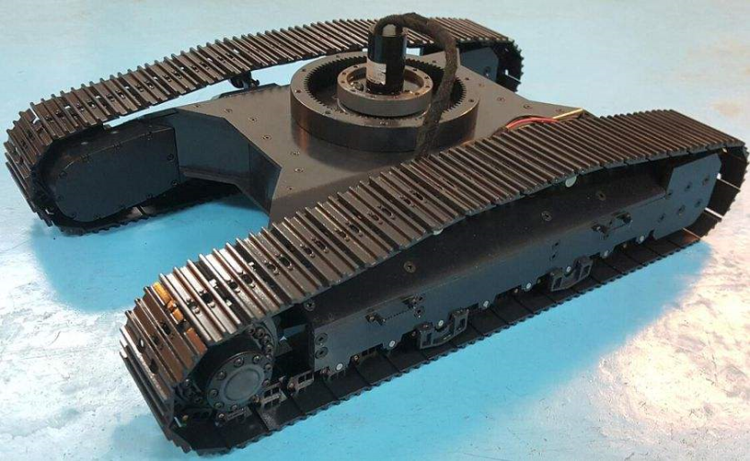
Track frame (X frame) -
the main structural part of the chassis part, connecting the four-wheel belt of the walking part, supporting the car body smoothly and realizing the walking of the machine.
Rollers
- Supports and distributes the weight of the machine evenly on the grounded tracks.
Support rollers
– hold up the rotating upper crawler so that the entire crawler can rotate smoothly.
track shoe
- evenly distribute the weight of the machine on the ground and realize the machine’s walking through its own rotation; increasing the contact area with the ground can reduce the ground specific pressure, so that the machine can walk on soft ground such as swamps and work; according to needs, users can choose to widen the track shoes or lengthen the track.
Idler wheel
—connected with the tensioning cylinder and tensioning spring to tighten the track and make the track tension appropriate; when the front of the track is impacted by external force, the impact force is transmitted to the tensioning spring through the guide wheel for buffering. Prevent track damage.
Final drive
- including traveling motor and traveling deceleration mechanism, as the driving wheel to provide power for the machine to travel, convert hydraulic energy into mechanical energy through the traveling motor, decelerate through the gear deceleration mechanism, increase the torque, and drive the track to rotate by the sprocket to realize the machine. walk
Post time: Jun-23-2022


